This lesson aims to provide an overview and a step by step guide to the radiological examination of impacted teeth to help gage the difficulty of extraction.
Incidence of impaction in third molars was reported to be as high as 75% in the European population [1]. Impaction of third molars are a common condition with which there are peri-operative risks including transient and/or permanent iatrogenic nerve injury [1]. Although some impacted third molar cases may often warrant specialist surgical intervention, this lesson will aim to provide an overview and a step by step guide to the radiological examination of impacted teeth to help gage the difficulty of extraction. Some of the radiologic principles when examining the radiograph will be revised from the special investigations lessons.
The third molar is located at the distal end of the body of the mandible, in proximity with the relatively thin ramus. It is good to note that this is an area of weakness that is prone to fracture if excessive force is used during elevation of the impacted tooth usually occurring when adequate preliminary bone removal hasn't been carried out [1]. The lingual alveolar bone in the region is also thinner than the buccal. A literature review about impacted third molars suggests the roots of third molars are in close proximity with the mandibular canal, in most cases. In some cases the roots can contact or penetrate into the mandibular canal or they can be deflected. More importantly, proximity of the molar roots with the canal has been associated with an increased risk of iatrogenic nerve damage peri-operatively [1]. In order to minimise the risk of peri-operative complications during 3rd molar surgery, several classifications were developed to assess the difficulty of the surgical procedure to allow adequate planning. For the purpose of this lesson we will discuss winters classification for 3rd molars and Parallax when assessing impacted canines.
When taking a radiograph of the impacted third molar the areas needed to carry out a thorough assessment are:
Periapical radiographs using a long cone paralleling technique have the advantage of reduction of radiation dose, reduction of magnification and a true relationship between bone height and adjacent teeth is demonstrated. The drawbacks of using only a PA radiograph is poor processing due to the flexibility of the film leading to a poor quality image. However, the biggest problem is that the mandibular canal cannot be clearly identified in the third molar region. Furthermore, the angulation of the PA film can affect the perceived location of the mandibular canal with the bone crest.
Panoramic radiographs are extra-oral radiographs which can provide broad coverage for the oral structures and transmits only 1/10 the dosage of full mouth radiographs [1]. The shortcomings of panoramic radiographs include: high distortion, phantom images, and a lower image resolution. This can consequently hide some important vital structures, e.g. cervical spine images overlapping the anterior aspect of the mandible. Furthermore it does not accurately project the buccolingual relation of the 3rdmolar to the inferior alveolar canal [1].
Cone Beam Computed Tomography (CBCT) can provide a 3D image of the 3rd molar and adjacent anatomical structure, this can be indicated in cases where the 2D radiograph demonstrates the mandibular 3rd molar being in close proximity with the mandibular canal [1]. CBCT can optimise risk assessment and aid surgical diagnosis and treatment planning. This was evident in a prospective study that evaluated the role of CBCT in patients considered to be at increased risk of alveolar nerve injury from the panoramic radiograph. However, after reviewing the CBCT images, a significant number of patients were reclassified to a lower risk for iatrogenic inferior alveolar nerve injury (IAN), and this change in risk assessment also resulted in a different surgical approach. Despite all the advantages of CBCT and all the detail it provides, it transmits significantly more radiation to the patient and therefore, only used when patients are perceived to be at an increased risk for IAN. This is in accordance to IRMER policies to keep the dose as low as reasonably possible (ALARP).
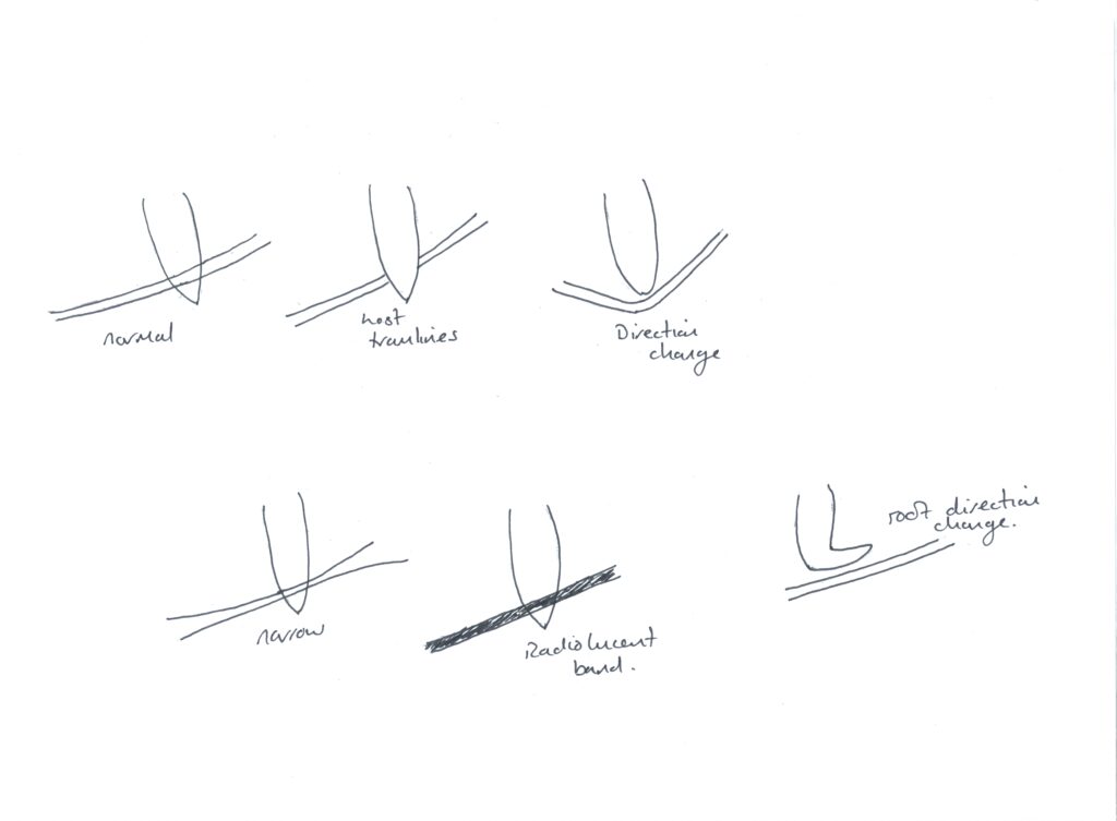
The main features that should be considered are [2, 3]:
This method involves the use of three imaginary lines drawn on a geometrically accurate PA radiograph.
1. The white line is drawn along the occlusal surfaces of the 1st and 2nd molars.
2. The amber line is drawn along the crest of the interproximal bone of the 1st and 2nd molar, extending distally along the internal oblique ridge, this indicates the margin of peri-coronal bone surrounding the 3rd molar.
3. The red line is perpendicular to the white line (1stline) and extends to the part of the crown where the elevator would be applied. If the length of the red line is greater than or equal to 5mm in length, the extraction is considered sufficiently difficult and sedation or GA may be indicated. Note: This measurement is taken from the point at which the red line crosses the amber line, and ends at the point of application.
1. The roots of the adjacent second molar are divided horizontally into thirds.
2. A horizontal line from the point of application of an elevator to the 2nd molar is drawn.
3. If the point of application lies opposite to the coronal, middle or apical 3rd of the root the extraction is assessed as being easy, moderate or difficult respectively.

Note:
The incidence of impacted upper canines has been reported around 1/100 [4], in addition, when impacted, canines have been found to overlap the adjacent lateral incisor in almost 4/5 of cases [5]. The upper canines should be present on buccal palpation at 9 years old, if not present this should be identify early as the child may need an orthodontic referral. The purpose of the radiographic assessment is to determine the location, size, shape, and any related pathology to the maxillary canine, as well as identifying any resorption of the adjacent lateral incisor. Impacted canines will require specialist intervention such as an orthodontist alongside the oral surgery team to plan whether intervention is necessary and discuss the risks and benefits with the patient.
Note: Canines have a long path of eruption, in addition to being the last tooth in the upper arch to come through (other than the 8); therefore, crowding can be a common occurrence preventing the canine from entering the arch. It is also important to remember our anatomy of the hard palate, as the greater palatine vessels and nerves are present; therefore, careful flap design and planning is needed to preserve these structures.
These radiographs may be used together to help ascertain the bucco-lingual location of the canine. This is of paramount importance when treatment planning, as it will influence the path of access, flap design and bone removal used.
Features that need to be examined include:
As for the wisdom tooth, the oral surgeon will look at the complexity of the extraction using the Winter's lines. When discussing the images of the canine and planning, the orthodontic needs to know the likelihood of the treatment success before they communicate to the surgeons to carry out the chosen procedure. Methods of doing this are:

Parallax is defined as: the apparent displacement of an object because of different positions of the observer [3]. This means if two objects are viewed, in two separate planes, are viewed from two different positions, the objects will appear to have moved in a certain direction.
A useful acronym to remember for parallax is the SLOB rule: Two radiographs are used and the question to answer is: Does the unerupted tooth move with the second position of the radiograph or opposite to the second radiograph? This can be carried out in the horizontal or vertical direction.
Same = Lingual / Opposite= Buccal.
This is the horizontal movement of the tube head of the X-ray.
This involves either:
Taking two PAs, e.g. one centred on the central incisor and the other at the impacted canine region.
OR/
A PA centred on the canine region with an upper standard occlusal centred in the midline. Note: the upper occlusal shows both sides of the arch.
This is the vertical movement of the tube head of the X-ray.
This involves a combination of one upper standard occlusal which is angled at 65-70 degrees, and a panoramic radiograph taken at 8 degrees.
Important: To make things a little more complex: We can look at the tooth as a whole, and decide which way it moves; however, using the methods above, the tooth could actually move in two directions.
Example:
CBCT allows the visualisation of the unerupted canine in different planes thus there is no need to use the principles of Parallax. However, this method transmits a higher dose of radiation to an often younger patient, so only used when necessary.
This lesson has focussed on the the 3rd molar and canine teeth. To further your revision please refer to the texts in our reference area and third party reading list.
IR(ME)R, 2018
Faculty General Dental Practitioners, n.d. Radiation doses and risks in dental practice. [Online] Available
Renton T, Woolcombe S, Taylor T, Hill CM. A clinical guide to oral surgery: Book 1. British dental journal. 2013.
Renton T, Woolcombe S, Taylor T, Hill CM. A clinical guide to oral surgery: Book 2. British dental journal. 2013.
Royal College of Surgeons guidelines RCS